Indicate the important assembly dimensions and write the item list. The Assembly and disassembly of Cotter Joint are quicker.

Machine Drawing Sleeve And Cotter Joint Socket And Spigot Joint And Knuckle Joint Geometric Drawing Autocad Joint
Circular rods Sleeve with Slots Cotters 130 010 130 130 Procedure 1.
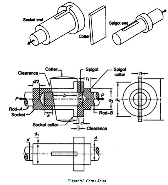
. Cotters are then inserted through slots to make assembly. One of the rods is formed into a socket by enlarging its end while the other rod called spigot end is formed with enlarged diameter and an integral collar The spigot is put inside the socket and the cotter is driven through the slots in socket and spigot ends. Cotter joint is widely used to connect the piston rod and crosshead of a steam engine as a joint between the piston rod and the tailor pump rod foundation bolt etc.
Machine vice and tailstock PO1 PO2 PO3 PO5 PSO1 PSO2 14 Assembly drawings Rams-bottom Safety Valve feed check valve PO1 PO2 PO3 PO5 PSO1 PSO2. This is the complete explanation of the Design Procedure for Cotter Joint and Knuckle Joint which is shown in a detailed manner. A love worth searching.
Screw jack PO1 PO2 PO3 PO5 PSO1 PSO2 13 Assembly drawings. Cotter joint with sleeve To draw the cotter joint with sleeve using Auto CAD. ASSEMBLY DRAWING The drawing which gives complete information of the object as a whole is called assembly drawing.
KEY S AND COTTER JOINT KEY-A piece of mild steel inserted between shaft and hub of mating member in axial direction. A universal joint and coupling assembly is disclosed which is utilized to connect and. Knuckle joint assembly drawing pdf Engineers Gallery Knuckle Joint Engineering Drawing Knuckle Joint Engineering Drawing Getting the books Knuckle Joint Engineering Drawing now is not type of inspiring means.
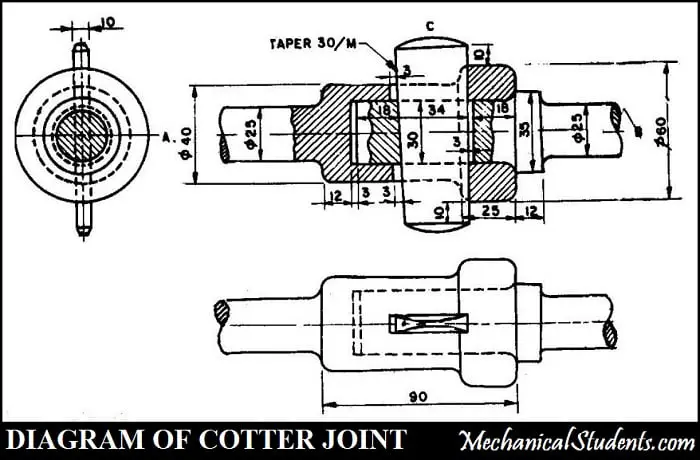
It is used for connecting rods which is subjected to axial forces in Engineering practice. Sometimes a sleeve and cotter joint as shown in Fig. Keys Cotter and 55 COTTER AND COTTER JOINT Knuckle Joints A cotter is a metallic strip of uniform thickness but tapers in width.
You can utilize the same for your own projects and can make changes to it in the properties. Spigot is formed on one of the rods and socket is formed on the other. Which are subjected to axial tensile or compressive forces.
0064 REFERENCE NUMBERS IN DRAWINGS 10 Universal and Coupling Assembly or Universal 12 positional. Assemblies tailstock radial engine bush type flexible coupling oldham coupling universal coupling Flange Coupling swivel bearing Foot Step bearing socket and spigot joint Sleeve and cotter joint knuckle joint claw coupling. A cotter joint is a temporary fastening and is used to connect rigidly two co -axial rods or bars.
Socket and spigot cotter joint is used to connect circular rods. Log off the system. 1 and 2 is used to connect two round rods or bars.
Connecting rod and eccentric PO1 PO2 PO3 PO5 PSO1 PSO2 12 Assembly drawings. Front view with top half in section 2. CAD EXERCISES FINAL BOOK-2pdf Contain Following Drawings.
Design of cotter joint. Sleeve Cotter Joint. 100 but may be as large as 1.
CAD Model of cotter joint assembly. CAD Model of cotter joint using CATIAV5R20. Elemental analysis at various loads.
Knuckle joint assembly drawing pdf Engineers Gallery Knuckle Joint Engineering Drawing Knuckle Joint Engineering Drawing Getting the books Knuckle Joint Engineering Drawing now is not type of inspiring means. See All Design To Learn to Design and assemble The Parts i. The locking device may be.
Stress and Deformation analysis along with GDT drawings. The cotter joint is withstanding the load applied during the working condition or not. Meshing of cotter joint using ANSYS R15.
COMPUTER AIDED MACHINE DRAWING 18ME36 KNUCKLE JOINT Draw the following views an assembled knuckle joint to 11 scale assuming the diameter of the rods d 20mm. Decimal Insertion scale Millimetres Insert line types Centre line and Dashed line into the drawing using Linetype command. You could not lonesome going past ebook addition or library or borrowing from your associates to admission them.
Exit the CAD software. Edit and save if necessary. Draw the required left hand side of cotter joint draw the cotter portion by using rectangle command Remove the sharp edges bu chamfer command Draw the shaft by using rectangle command and draw the sleeve by using rectangle command Draw arc for the sleeve by using arc command Click hatch command angle 45 degrees line to line distance 2mm.
RESULT Thus the 3D assembly of the knuckle joint has been created on the software CATIA V5 with accurate dimension and with all respects. In this type of joint a sleeve or muff is used over the two rods and then two cotters one on each rod end are inserted in the holes provided for them in the sleeve and rods. Cotter Joint for Circular rods Socket and spigot.
Knuckle joint assembly drawing pdf Engineers Gallery Download Ebook Knuckle Joint Engineering Drawing categories to choose from that occupy a space of 7191GB. A view from the eye end of the rod. Set limits of Auto CAD screen.
Download PDF Find Prior Art Similar. 11 Assembly drawings. Part modelling Part design.
Cotter Joint has mainly three components spigot socket and cotter as shown in Figure 91. The rods are inserted through the ends of the sleeve and meet each other at the centers. The two slots in the sleeve and corresponding two slots near the end of the rods are provided to suit cotters.
Training Video For professional Designer. You could not lonesome going past ebook addition or library or borrowing from your associates to admission them. Set units Type.
A good assembly drawing should satisfy- 1. The cotter joint has been designed using Fusion having taken Design stress and FOS considerations. The taper may be very small like 1.
The remaining part for the design procedure of a cotter joint is presented in the form of a video which is shown below. Up to 24 cash back Open the assembly part then open the all parts one by one. The cotter passes through slots made in two coaxial parts and thus prevent the relative motion between them.
Assemble the parts by using the tools. The best part is that it does not need you to register and lets you download hundreds of free eBooks related to fiction science engineering and many more. Autocad 3D Machine Drawing Assembly Learn In easy Way.
Sleeve and Cotter Joint. P So the methodology of the study includes 1. Types of gear pdf gib and cotter joint socket and spigot joint classification of brakes types of fire in hindi application of cotter joint different types of brakes and their applications type of fire in hindi arduino projects ideas mechanical drill knuckle joint application application of knuckle joint type of gear difference between cotter joint and knuckle joint socket and.

Assembly Of Sleeve And Cotter Joint Engineering Drawing Engineering And Poetry Youtube

Pin On Cad
Design Procedure For Knuckle Joint Cotter Joint Formulas Pdf
Machine Design Lesson 9 Design Of Cotter Joint

31 Cotter Joint Final Pdf Computer Aided Design Autodesk

Machine Drawing Sleeve And Cotter Joint Socket And Spigot Joint And Knuckle Joint Joint Autocad Drawing Exercises

Machine Drawing Sleeve And Cotter Joint Socket And Spigot Joint And Knuckle Joint
Figure Shows The Details Of The Parts Of An Socket And Spigot Cotter Joint Assemble These Parts Correctly Sarthaks Econnect Largest Online Education Community
0 comments
Post a Comment